🔘 Push Button Switch Panel
The human interface to your automation system
🔧 Overview
Push button panels are the primary user interface for your home automation system. Unlike wireless switches that can lose connection or have battery issues, hardwired illuminated push buttons provide instant, reliable control.
Each panel contains up to 4 illuminated push button switches with individual LED illumination, allowing users to see the switch even in darkness. The industrial approach uses low-voltage signaling for safety and reliability.
Why Illuminated Push Buttons?
- Instant Response: No wireless delays or connection issues
- Night Operation: Dimmable illumination for comfortable night use
- Tactile Feedback: Physical confirmation of button press
- Wife Acceptance Factor: Familiar interface that everyone can use
The switch panels are manufactured from standard wall plates with precision-drilled holes to mount 16mm illuminated push button switches. This approach provides a professional appearance while maintaining industrial reliability standards.
📋 Technical Specifications
| Parameter | Specification | Notes |
|---|---|---|
| Operating Voltage | 5V DC (button logic) / 6-12V DC (LED illumination) | Safe extra-low voltage operation |
| Contact Rating | 5mA per button @ 5V DC | Signal level switching only |
| LED Current | 10mA per button @ 12V | Series resistor required for <4 switches |
| Cable Requirements | Ethernet cable with RJ45 modular plugs | T-568A/B standard |
| Panel Configuration | Up to 4 illuminated push buttons per panel | Standard wall plate size |
| Switch Type | 16mm illuminated push button | SPDT contacts with LED |
| Installation Height | 1.2m from floor | Standard switch height |
🛡️ Safety Note
All button circuits operate at safe extra-low voltage (5V DC & 12V DC). Mains voltage switching is handled remotely by relays in the control room, eliminating shock hazards at user interfaces.
🔌 Wiring & Installation
Installation Steps:
- 1. Get 2 spools of Ethernet cable
- 2. Mark one spool with an 'A' and the other 'B'
- 3. Place spools near where input circuit boards will be located
- 4. Mark cables according to spool marks ('A' or 'B')
- 5. Tape the 2 loose ends together
- 6. Pull straight out to ceiling/under floor to panel locations
- 7. Allow good length spare at each end
- 8. Mark each cable at both ends with cable number
- 9. Cover markings so painter doesn't paint over them
- 10. Coil up cable end and hang from wall plate mounting bracket
- 11. Mark floor location to find bracket after wall cladding
Cable Installation Process
It's best if you run the required cable and add a spare. If a core fails in years to come, you will have a backup (it most likely won't fail because you ran a spare - Murphy's law).
Cable Termination
Use standard Ethernet cable with RJ45 modular plugs installed on both ends following the T-568 convention. Like a lot of things, this convention has 2 variations:
- T-568A: Used in Australia, keeping backward compatibility with the old phone system
- T-568B: Used just about everywhere else in the world
Important: It doesn't matter which standard you choose as long as you stick with the same convention at both ends of the cable.
RJ45 Connector Pin Configuration
The RJ45 connector pin layout and color coding follows the standard Ethernet wiring conventions:
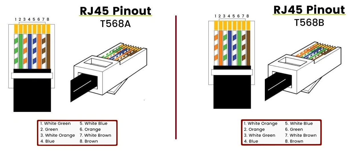
RJ45 Pin Configuration showing T-568A and T-568B wire color standards
How to Crimp RJ45 Plugs onto Ethernet Cables
Proper termination of RJ45 connectors is crucial for reliable operation. Follow these steps for professional results:
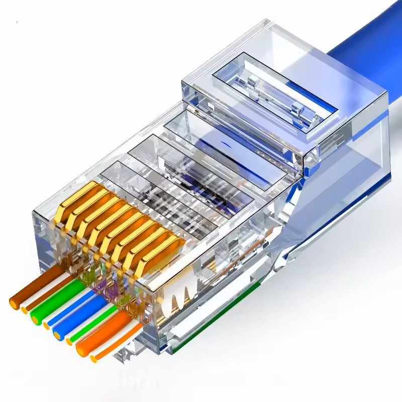
RJ45 pass Through Connector
Easy connection of RJ45 connector
Step-by-Step Crimping Process:
- Slide a strain relief boot onto the cable
- Carefully cut about seven centimetres of insulation off the wires
- Remove the plastic divider used for decreasing crosstalk and ripcord thread from the exposed section
- Untwist the wires and firmly stroke them to straighten them out
- Place the wires in the correct order as per T-568A or T-568B (whichever preferred)
- Get an RJ45 pass-through connector and starting from one side, pass the first wire into the connector and through the connector, making sure of correct orientation
- Continue with the next wire making sure there is no gap between the wires
- Move the connector firmly back on the wire so that the strain relief holds on the outer jacket
- Put the filled connector into the RJ45 crimper and crimp firmly
- Carefully remove the excess wires hanging out of the connector with a sharp knife
- Once both ends of the cable have been terminated, test the cable using a network cable tester
Required Tools
Professional cable termination requires the right tools for reliable results:
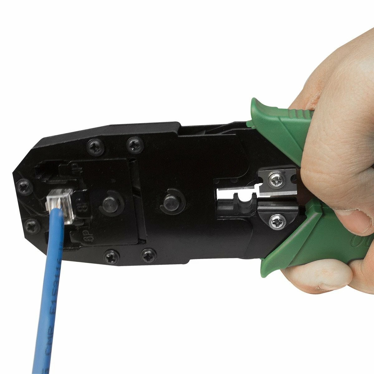
RJ45 Crimping Tool
Professional crimper for secure connector termination
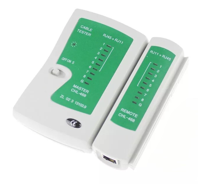
Network Cable Tester
Essential for verifying proper cable termination
💡 Pro Tips for Crimping Success:
- Use pass-through RJ45 connectors for easier wire alignment
- Keep wire pairs twisted as close to the connector as possible
- Ensure the outer jacket extends into the connector for proper strain relief
- Test every cable - a cable tester will save you hours of troubleshooting later
Pro Tip: It's easy to cut off excess cable but bloody hard to join it on. Always err on the side of too much cable!
⚡ Electrical Drawings & Schematics
Panel Wiring
The easiest way to make connection onto the RJ45 plug is by using a RJ45 breakout board which is readily availave et such places a sparkfu, Ebab and AliExpress
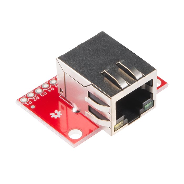
RJ45 Breakout Board
Easy connection of RJ45 plug to wiers
Switch Panel Internal Wiring
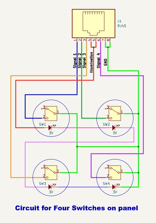
Circuit for 4 Pushbutton switches
No series resistor for 4 panels
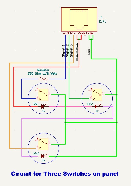
Circuit for 3 Pushbutton switches
Using 330 ohm 1/8 Watt dropping resistor
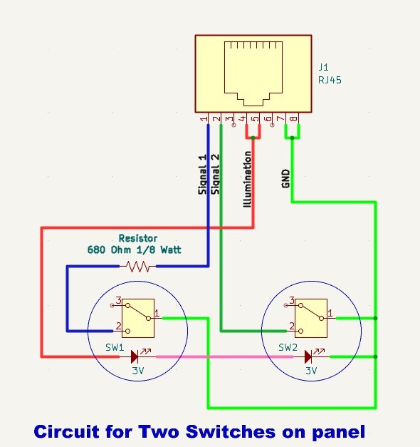
Circuit for 2 Pushbutton switches
Using 680 ohm 1/8 Watt dropping resistor
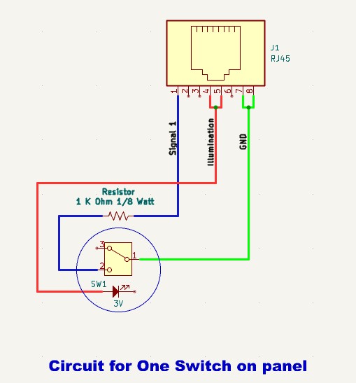
Circuit for 1 Pushbutton switch
Using 1000 ohm 1/8 Watt dropping resistor
Push button connections
I used readily available Illuminated Push button switches, but it's personal preferance as long as the button is a momentary contact ( the signal is connected to ground as long as your finger is on the button).
🔍 Panel Assembly
Assembly Instructions
- Wall Plate Drilling: Mark and drill 16mm holes using template
- Switch Installation: Mount switches with provided nuts and washers
- Wiring: Connect switches to breakout board according to pin configuration
- LED Circuit: Wire all LED positives in parallel to Pin 4, LED negatives to Pin 5
- Testing: Verify all connections with multimeter before installation
Quality Control Checklist
- ✓ All holes drilled to exact 16mm diameter
- ✓ Switch mounting secure with no movement
- ✓ LED illumination functional at 12V
- ✓ Contact continuity verified on all buttons
- ✓ RJ45 connector properly terminated
- ✓ Cable test passes all pins
- ✓ No short circuits between any pins
🔍 Troubleshooting
Common Issues and Solutions
LED Not Illuminating
- Check 12V power supply to Pin 4 (Blue wire)
- Verify ground connection on Pin 5 (White/Blue wire)
- Test LED with external 12V supply
- Check for reversed polarity
Button Press Not Detected
- Verify continuity between COM and NO contacts when pressed
- Check signal wire connections (Pins 1, 3, 7, 8)
- Test with multimeter in continuity mode
- Inspect for loose terminal connections
Intermittent Operation
- Check RJ45 connector for proper crimping
- Inspect cable for damage or kinks
- Verify all terminal block connections are tight
- Test cable with Ethernet cable tester
⚠️ Important Safety Notes
- Always disconnect power before working on panels
- Use only specified low voltage supplies (5V, 12V DC)
- Never exceed 15V DC on LED circuits
- Ensure proper cable strain relief at all connections